Lab 2: Analog Circuitry and FFTs
In this lab, we added sensors to the robot.
One is a microphone circuit that will detect a 660Hz whistle blow signifying the beginning of the maze mapping. The other will capture inputs from an IR sensor to detect nearby robots emitting IR at 6.08kHz, and distinguish them from decoys emitting at 18kHz.
Open Music Labs FFT Library
Data was collected from the ADC (for the optics team) or from analogRead (for the acoustics team) and transformed via the FFT library. The Arduino FFT library allows users to quickly transform signal data gathered over a period of time from the Arduino into its various frequency.
Acoustic Team
Priya and Vini worked on the acoustic functionalities.
Assembling the microphone circuit.
- 1 Arduino Uno
- Electret microphone
- 1 µF capacitor, 6.8µF capacitor
- various resistors
- LM358 Op Amp
- Various wires

We first connected the microphone to the arduino using the diagram above as reference. We used a 3.24KΩ Resistor and a 1µF Capacitor. We connected the output to pin A1.
In Arduino the ADC clock is preset to 16 MHz/128 = 125 KHz (though the sampling rate can be increased). Each conversion in AVR takes 13 ADC clocks so so the equivalent frequency is 125 KHz /13 = 9615 Hz. The ‘start’ is signaled by 660Hz, so analogRead is sufficient to fulfill the Nyquist Criteria which requires that the sampling frequency is at least twice the highest frequency component to avoid aliasing. The frequency of the human speech 85-180 Hz for males and 165-255 for females, and so should not interfere with sensing the start signal.
We hooked up the function generator to the Input of the circuit to test which bin the 660Hz signal would fall in.
We used the following code, modified from Team Alpha, to collect values:
void setup() {
  Serial.begin(115200); // use the serial port
}

void loop() {
  while(1) {
    cli();
    for (int i = 0 ; i < 512 ; i += 2) {
      fft_input[i] = analogRead(A1);
      fft_input[i+1] = 0;
    }
    fft_window();
    fft_reorder();
    fft_run();
    fft_mag_log();
    sei();
    Serial.println("start");
    for (byte i = 0 ; i < FFT_N/2 ; i++) {
      Serial.println(fft_log_out[i]);
    }
  }
}

The 660Hz input from the function generator peaked at bin 20, whereas the 500Hz signal peaked at bin 15 and the 750Hz signal peaked at bin 22. This shows that the circuit can decipher between signals that are close together.
We also see peaks at bins 1 and 2 for all signals, due to DC values at the input. Since these are consistent for all frequencies, we can ignore these peaks.

We then added the above amplifier circuit, from Team Alpha, as recommended by the TA’s.
The exact resistor values are: 328Ω, 3.24kΩ, 391kΩ, 9.85kΩ, 9.8kΩ

We then tested the microphone with a 660Hz tone being played, instead of directly inputting a signal from the function generator. We collected the values using the same code as before. As seen in the graph above, without the amplifier the 660Hz tone blends in with the other signals. With the amplifier connected, we can see a peak at bin 20, which is where we saw the 660Hz peak with the function generator. There are also peaks at bin 39 and 58, most likely due to background noise in the lab. This shows that the circuit is successful in amplifying the 660Hz value above noise, and can identify the 660Hz tone based on which bin it appears in (bin 20).
Optical Team
Joyce and Nathalia worked on the optical functionalities.
Assembling the IR Circuit
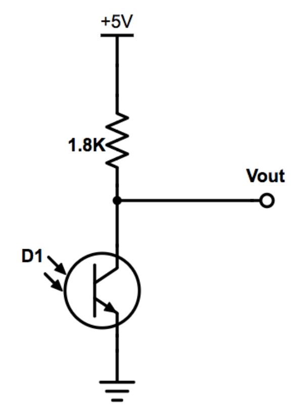
The first step of unit testing was understanding the phototransistor. We know that phototransistors measure the light intensity and lets more current pass the more light it receives. As given in the prompt, the IR hat emits 6.08kHz and we need to ignore decoys of 18kHz.
We first connected the photoresistor according to the circuit above. When powered up, we checked for functionality using our phone cameras. Because the cameras don’t have an IR filter, the photoresistor would glow blue, even though our naked eyes wouldn’t pick up anything.
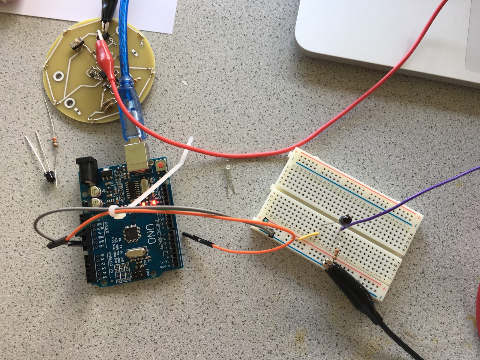
We didn't have the 9V battery so we connect the IR hat to the DC power supply, set to 9V. The oscilloscope is connected to the output and the ground to measure the signal. This unit test is done without additional circuit.
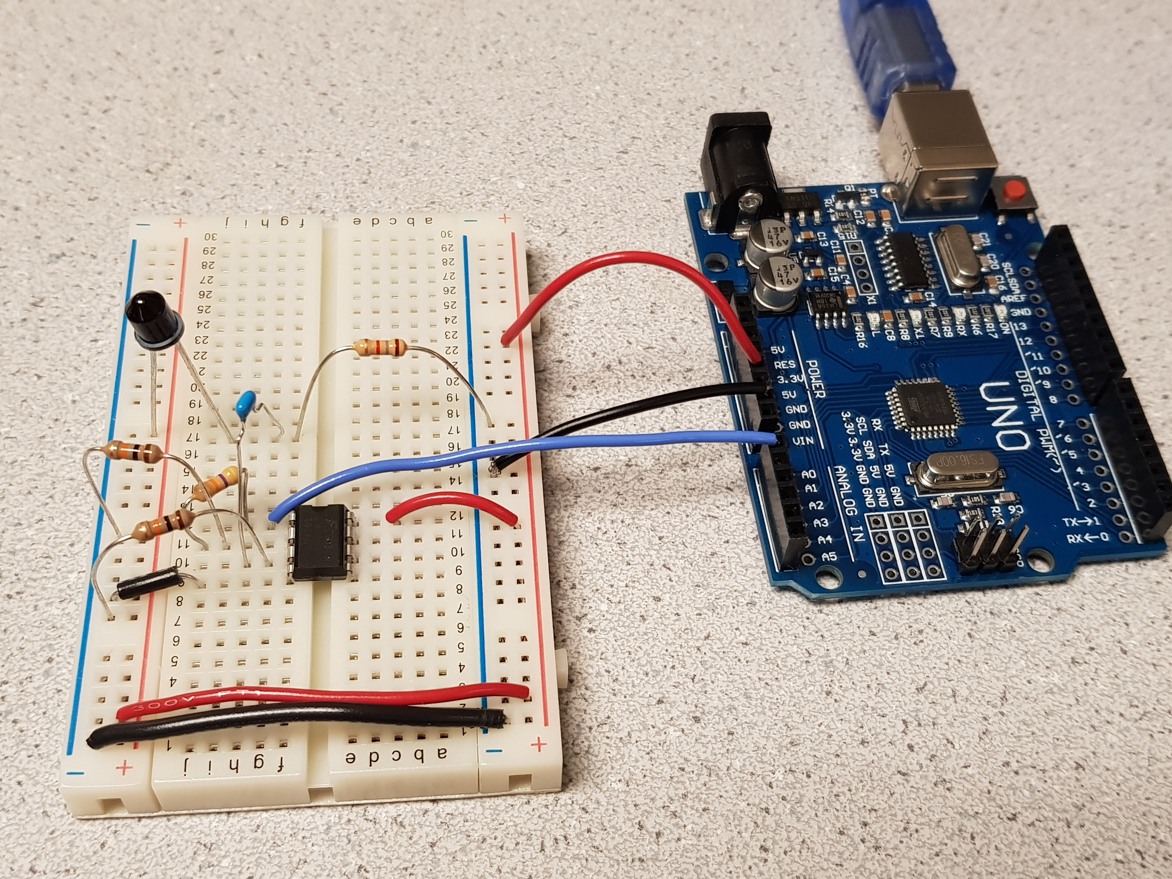
Consequently, we had to add an operational amplifier. Without an op amp, the sensor cannot detect the IR waves unless the emitting source is in close proximity. To only detect the 7kHz signal. We compute the bin number of which 7kHz would be present. We determined the bin number is 45 to 50, so we read values from those bin only. When they peak, we output that the treasure is detected.
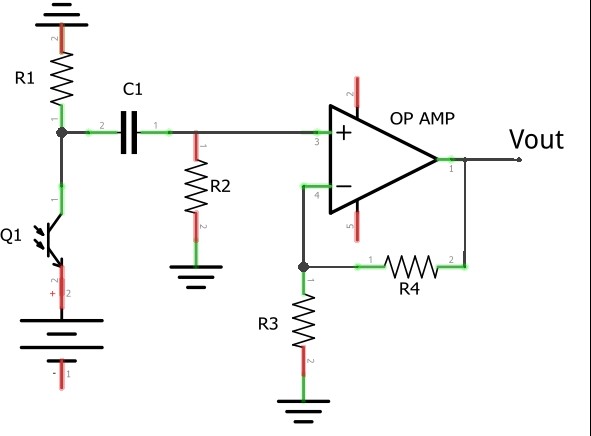
| Component Part | Value |
|---|---|
| R1 | 1.34 kΩ |
| R2 | 6.79 kΩ |
| R3 | 6.73 kΩ |
| R4 | 39.93 kΩ |
| C1 | 3.3 nF |
Main loop
void loop() {

  while(1){
    cli(); //UDRE interrupt
    for(int i = 0; i < 512; i+=2){
      while(!(ADCSRA & 0x10)); //waiting for adc to be ready
      ADCSRA = 0xf5; //restart ADC
      byte m = ADCL;
      byte j = ADCH;
      int k = (j << 8) | m;
      k -= 0x0200;
      k <<= 6;
      fft_input[i] = k;
      fft_input[i+1] = 0;
    }

    fft_window();
    fft_reorder();
    fft_run();
    fft_mag_log();
    sei(); //turns interrupts back on

    Serial.println("start treasure hunt");
    for (byte i = 0; i < FFT_N/2; i++){
      Serial.println(fft_log_out[i]);
    }

    trasureDetect();
  }

}
An example of one loop inside the treasure detection subroutine. This is repeated of bin sizes of 7 (as below), 12, and 17. Once the value for each bin's maximum value is tested for, the code runs through a conditional loop to compare the max value to the constant value thresholds. Should the stored value be greater than the threshold, it prints to the serial monitor the corresponding treasure value.
  int max_7_bin = 0;
  for (int i = 46; i < 50; i++){
    int x = (int) fft_log_out[i];
    if(x > max_7_bin){
      max_7_bin = x;
    }
  }
Work Distribution
The Lab 2 Work Distribution is as follows:
- Priya and Vini worked on the acoustics circuit
- Joyce and Nathalia worked on the optical circuit
The Lab 2 Report Work Distribution is as follows:
- Priya and Vini worked on the acoustics circuit write up
- Priya finished the acoustics graphs
- Joyce and Nathalia worked on the optical circuit
- Joyce filmed the video
The website work distribution is as follows:
- Nathalia: Website Set Up and Lab 2