Lab 1: Microcontroller
This lab is an introduction to the Arduino IDE. The team is split into two subteams to perform the same tasks. In the end of the lab, both subteams were able to control the LED and servo, which are then used to build the robot below.
Communicating between Uno and IDE
In order to test the Arduino UNO and the IDE, we used example code “Blink.” This program caused an LED on the Arduino to blink on and off every other second. The LED on board is connected to pin13, which is also defined as LED_BUILTIN in the macro. The delay loop takes the value of 1000 which corresponds to 1 second.

                // the setup function runs once when you press reset or power the board

                void setup() {

                    // initialize digital pin LED_BUILTIN as an output.

                    pinMode(LED_BUILTIN, OUTPUT);

                }


                // the loop function runs over and over again forever

                void loop() {

                    digitalWrite(LED_BUILTIN, HIGH);   // turn the LED on (HIGH is the voltage level)

                    delay(1000);                       // wait for a second

                    digitalWrite(LED_BUILTIN, LOW);    // turn the LED off by making the voltage LOW

                    delay(1000);                       // wait for a second

                }
Modify the blink sketch
We modified the example code blink.ino so that it would work for an external LED. We tested the digital input ports 2-12 to make sure they were all functional. In order to switch which port is being sent information, we need to change LED_BUILTIN to the number of the port we need to access. The below code is set to work for an LED connected to port 2. (Note: When testing the different ports, we attempted to use ports 0 and 1 but were unable to do so -- we discovered that this is because ports 0 and 1 are typically used for serial communication.)

                // the setup function runs once when you press reset or power the board

                void setup() {

                    // initialize digital pin LED_BUILTIN as an output.

                    pinMode(2, OUTPUT);

                  // int PINNAME = A2

                }


                // the loop function runs over and over again forever

                void loop() {

                    digitalWrite(2, HIGH);   // turn the LED on (HIGH is the voltage level)

                    delay(1000);             // wait for a second

                    digitalWrite(2, LOW);    // turn the LED off by making the voltage LOW

                    delay(1000);             // wait for a second

                }
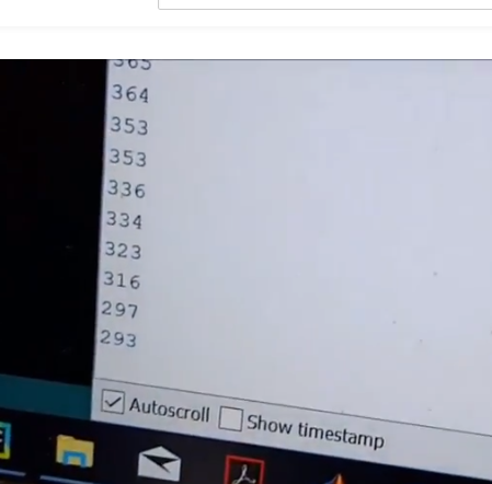
The Serial Monitor and the Analog Pins
We used a potentiometer to measure the analog voltages from the input pins. To write to the serial monitor we first opened the serial port at 9600 bits per a second as per the documentation. We then used the inbuilt analogRead method to collect readings from the potentiometer. These values were then printed to the serial interface through the println method. The delay method takes input in milliseconds so to get a reading every half second we set a delay of 500.
                int pinPot = A0;

                int val = 0;


                // the setup function runs once when you press reset or power the board

                void setup() {

                    Serial.begin(9600);      // open the serial port at 9600 bps:

                }


                // the loop function runs over and over again forever

                void loop() {

                     val = analogRead(pinPot);   // read the input pin

                     Serial.println(val);

                     delay (500);

                }
Analog Output
This was an extension of Part 3. Here, as before we used analogRead to get values from the potentiometer. We then used the analogWrite function so that the brightness of the LED would be dependant on the potentiometer readings. As in the modified blink code, the pin corresponding to the LED was set to output in the setup. To compensate for the difference in the range of possible analogRead (0-1023) and analogWrite (0-255) values the value assigned to the LED was one-fourth the value read by the potentiometer; thus while there was a direct relationship between the potentiometer readings and brightness it was not one-to-one.
                int pinPot = A0;

                int val = 0;

                int ledpin = 3;


                // the setup function runs once when you press reset or power the board

                void setup() {

                   pinMode(ledpin, OUTPUT);   // sets the pin as output

                   Serial.begin(9600);      // open the serial port at 9600 bps:

                }


                // the loop function runs over and over again forever

                void loop() {

                     val = analogRead(pinPot);   // read the input pin

                     Serial.println(val);

                     analogWrite(ledpin, val / 4);  // analogRead values go from 0 to 1023, analogWrite values from 0 to 255

                     delay (100);c
                }
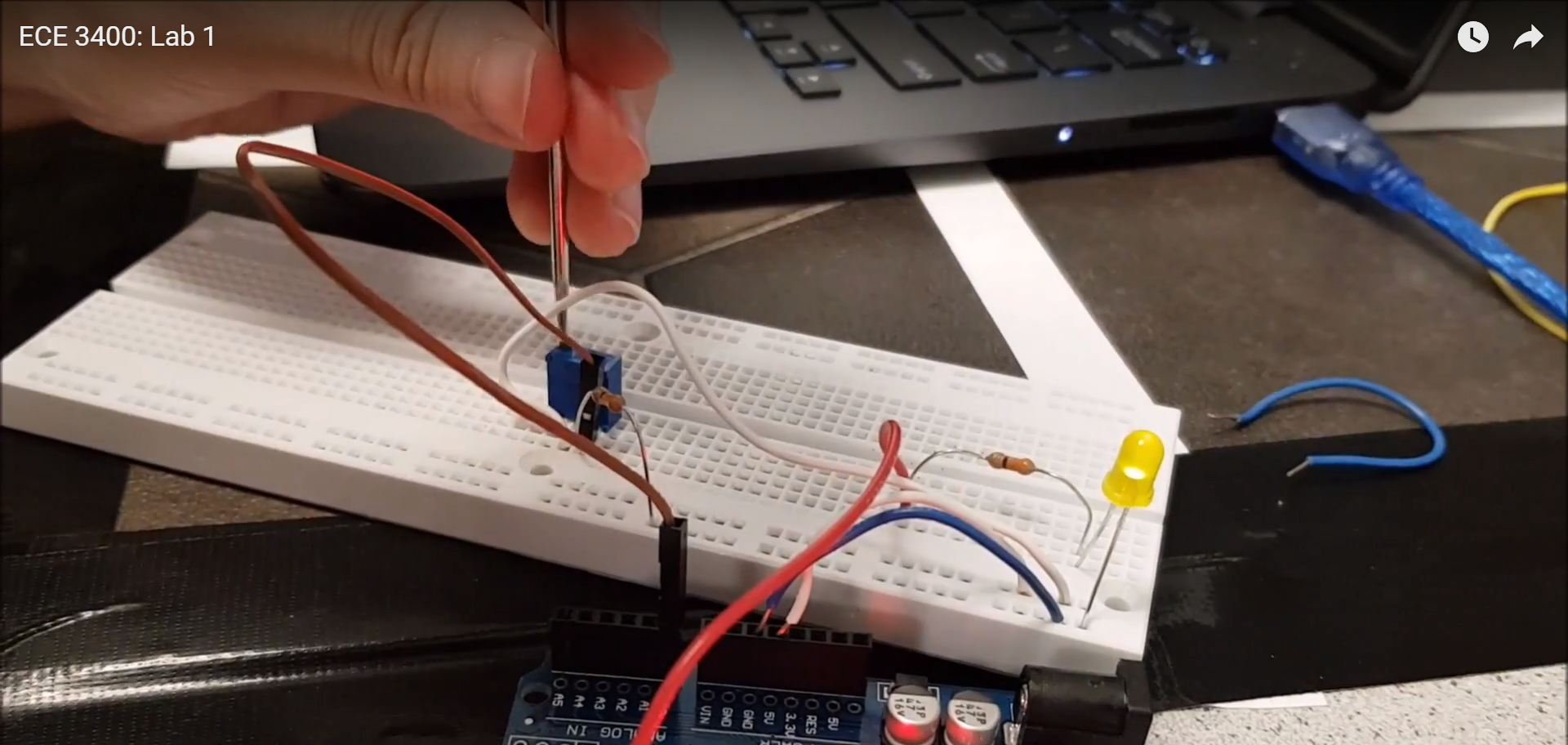
Parallax Servos
During this portion of the lab we practiced using servo motors in different ways with the aim of becoming more comfortable and experienced. Our chosen exercises were particularly the degree of control we had over the angle. In the first code was written to obtain a general understanding of what how servo motors moved. Accoridng to the documentation, the servo would stop at value of 90. We then use this value to calibrate the servo using the small screw on the side of it. Note that when connected to the Aruidno board, the servos must be connected to the PWM pins.

                #include Servo.h


                Servo servo_1;

                int pos = 0;


                // the setup function runs once when you press reset or power the board

                void setup() {

                    Serial.begin(9600);

                    servo_1.attach(9);

                    //servo_1.write(90);  // set servo to mid-point:

                }


                // the loop function runs over and over again forever

                void loop() {

                 //servo_1.attached();

                  for (pos= 0; pos <= 180; pos+=1){

                       servo_1.write(pos);

                       Serial.println(pos);

                       delay (100);

                  }

                  for (pos = 180; pos >= 0; pos-=1){

                       servo_1.write(pos);

                       Serial.println(pos);

                       delay (100);

                   }

                }


                *****************************************************************


                #include Servo.h


                Servo servo_1;

                int pos = 0;


                // the setup function runs once when you press reset or power the board

                void setup() {

                    Serial.begin(9600);

                    servo_1.attach(9);

                    //servo_1.write(90);  // set servo to mid-point:

                }


                // the loop function runs over and over again forever

                void loop() {

                    //servo_1.attached();

                    for (pos= 0; pos <= 89; pos+=1){

                       servo_1.write(pos);

                       Serial.println(pos);

                       //delay (100);

                  }

                  for (pos = 89; pos >= 0; pos-=1){

                         servo_1.write(pos);

                         Serial.println(pos);

                         //delay (100);

                   }

                }
Assemble the Robot
Our robot has a purple base plate, and green feet that hold servo motors, which are attached to the wheels. The Arduino UNO is attached to the top of the base plate, and the mini-breadboard is connected to the robot by the wires of the servo motors. The power bank is attached to the front of the robot in order to keep it stable. It is held steady by green wires that tie it to the base plate. The following code is the movement demonstrated in the video. The robot goes in one direction for 3 seconds, turns right for 3 seconds, and continues repeating that pattern.

                #include Servo.h

                Servo servo_L;

                Servo servo_R;


                int pos = 0;


                void setup() {

                    // put your setup code here, to run once:

                    Serial.begin(9600);

                    servo_L.attach(3);

                    servo_R.attach(4);

                }


                void loop() {

                    // put your main code here, to run repeatedly:

                    // make the robot move in a straight line

                    servo_L.write(180);

                    servo_R.write(0);    // for 3 seconds

                    delay(3000);         // make the robot turn right

                    servo_R.write(90);

                    servo_L.write(180);  // for 3 seconds

                    delay(3000);

                }
Work Distribution
The Lab 1 Work Distribution is as follows:
- On 8/31, Nathalia, Priya and Vini worked on steps 1-5 and began part 6.
- On 9/4, Priya and Nathalia attended open Lab to complete Part 6.
- On 9/7, Joyce reassembled the robot.
The Lab Report Work Distribution is as follows:
- Vini: Part 3, Part 4, Part 5, code snippets
- Priya: Materials Used, Part 1, Part 2, Part 6, code snippets
- Nathalia: All Pictures and Videos
The website work distribution is as follows:
- Nathalia: Website Set Up and Lab 1
- Joyce: Overview, Website Design, index.html and css