Final Design
FINALLY. The final design. All the blood, sweat, and tears this semester culminating up to this one point...
This semester in ECE 3400, we created our robot, lovingly named NVR (which stands for Nice Voyager Robot). NVR can follow lines, avoid walls, and send his explorations to a nearby base station! Read on to learn about what NVR can do and how he does it!
Hardware Unit Description
Materials
- 1 Arduino Uno
- 2 breadboards
- 1 Power Bank
- 1 9V Battery
- 1 IR emitting hat
- 2 Parallax Continuous Rotation Servos
- 3 Line sensors
- 3 Wall sensors
(one short range, two long range IR proximity sensors)
- 1 Microphone
- 1 IR phototransistor
- 2 Radios (nRF24L01+) and breakout board
- 1 Pushbutton
- Various resistors and capacitors
- Various mechanical components (wheels, mounts, etc.)
| Item | Quantity | Cost |
|---|---|---|
| Line Sensors | 3 | $9 |
| IR distance sensors | 3 | $21 |
| Parallax servos | 2 | $26 |
| Arduino Uno | 1 | $16 |
| Radio | 1 | $1.25 |
| 9V Battery | 1 | $1.20 |
The total comes to be $74.45, which is under $100 as needed.
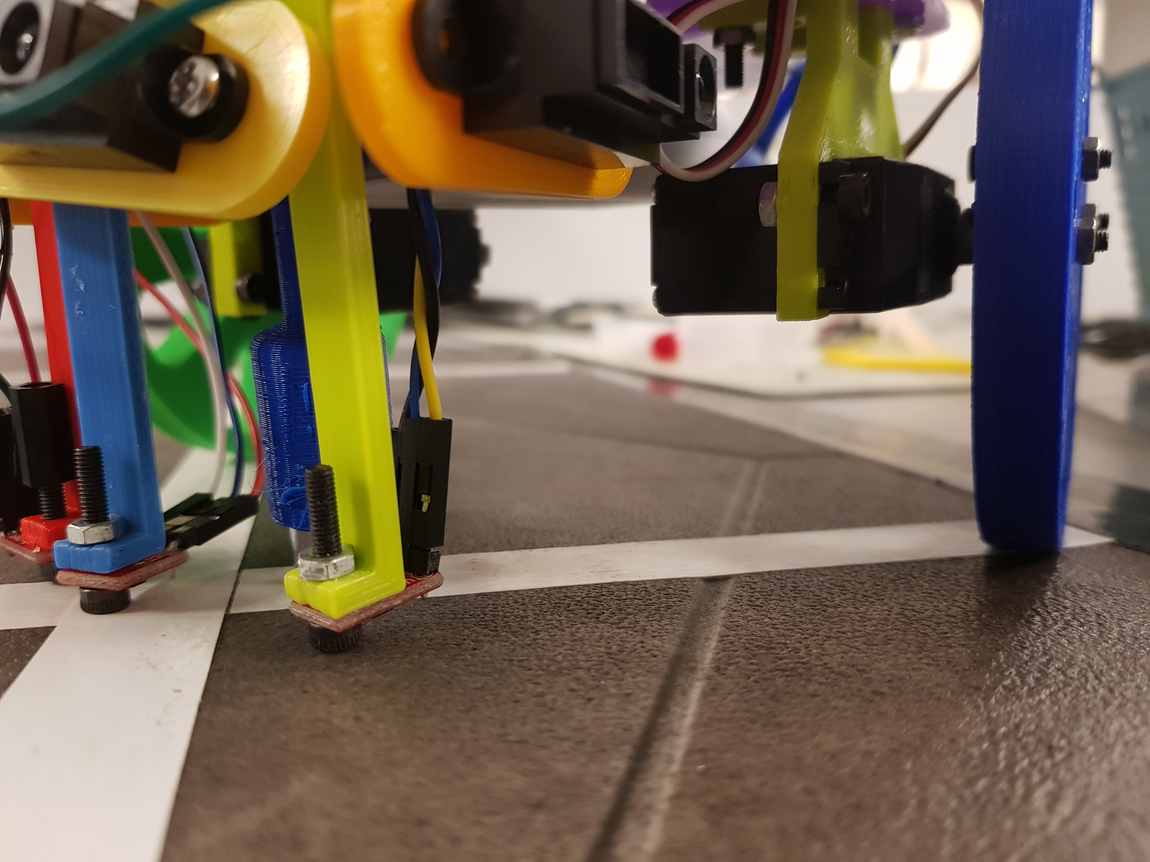
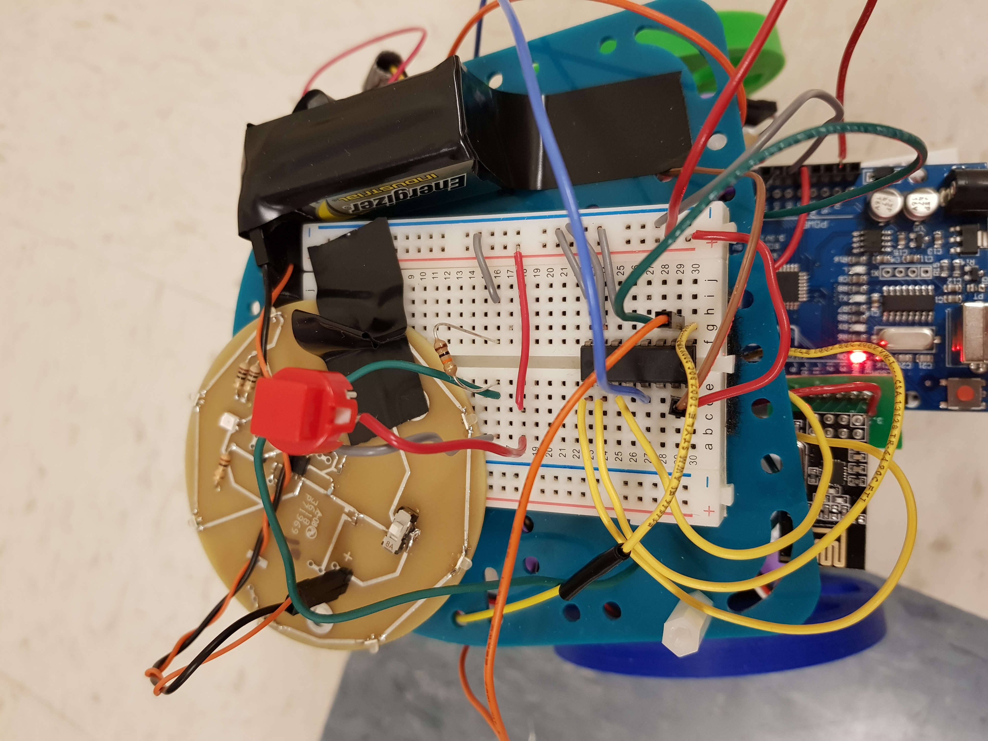
Layer Zero
Layer zero holds the servos and the line sensors. The battery is also fastened on this level. The servos make the wheels turn, to help NVR explore the maze. The line sensors keep NVR on track during his adventures.
The servos are connected to digital pins 5 and 6. Setting different values to the servos determines how fast and in what direction the servo moves. We connected each servo to a wheel, thus allowing NVR to move. Here’s an example of how we control how NVR travels:
void move(int direction){
  //look for intersection
  while(1){
    Serial.println("looking");
    read_turn();
    if (left_turn_val < WHITE && right_turn_val < WHITE){
      i = 0;
      Serial.println("found intersection");
      while(i < 30){
        go_straight();
        i++;
      }
      break;
    }
    go_straight();
    delay(10);
  }//close while, found intersection

  // Turn if requested, white=700
    if(direction == right){
      Serial.println("TURN RIGHT");
      left_servo.write(95);
      right_servo.write(95);
      while(analogRead(left_turn) > WHITE);
      while(analogRead(left_turn) < WHITE);
      while(analogRead(left_turn) > WHITE);
      Serial.println("done turn right");
    }
    //similarly for turning left
}
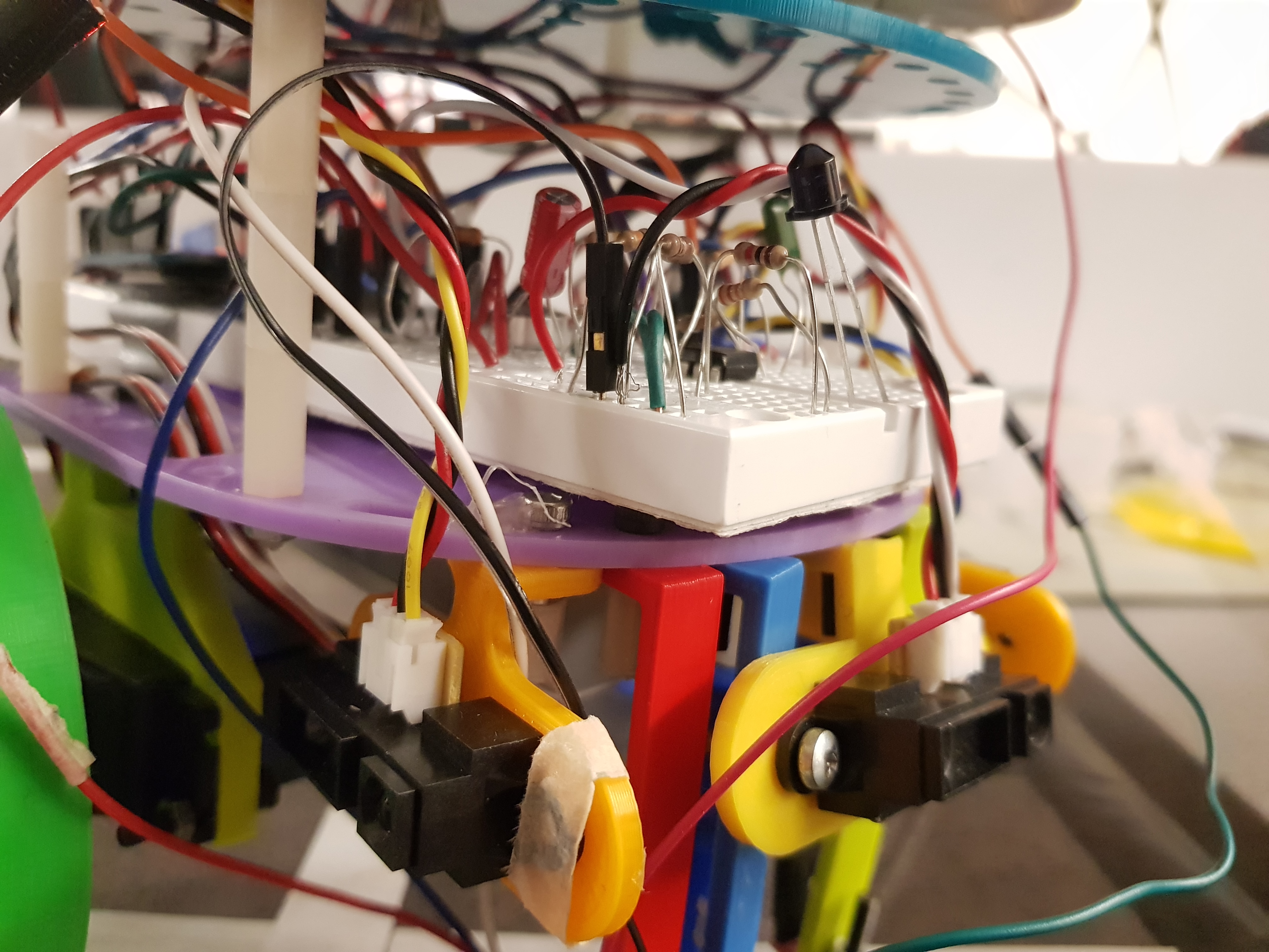
Layer One
On layer one you can find the acoustic circuit, IR circuit, the wall sensors, and the radio. This level also houses the arduino, which is NVR’s brain. The acoustic circuit searches for a 660Hz signal that tells NVR it’s time to begin his travels. The IR circuit helps NVR communicate with other robots, so he doesn’t run into them on his journey, and they don’t run into him. The wall sensors help NVR avoid walls and help him decide which way to go. The radio allows NVR to map out his journey.
In order to detect the 660Hz tone, we added the acoustic circuit, whose schematic is pictured below. This microphone detects sound and the frequency is amplified. We look at the frequencies by organizing them into bins. The 660Hz tone appears in bin 17. Therefore, if 660Hz tone is playing, the magnitude of bin 17 will be greater than if there was just noise. Therefore, if this magnitude reaches a certain threshold value, NVR can tell if the tone is being played, and he will start exploring. We’ve found that NVR usually hears the sound, but just in case he doesn’t, we’ve also added a pushbutton that will also us to manually tell NVR to start exploring. The pushbutton circuit and functionality is described on layer 2.
The IR hat will emit 18kHz for other robots to detect our robot. At the same time, the robot will detect other robots with the phototransistor. In the final design, the robot detection code is in main loop, polled continuously. This function needs to first disable the timer and then run the detection, then reset the timer.
The walls in the maze limit the directions that NVR is allowed to travel. In order to give him a wide view of the maze, we added 3 wall sensors. With a line sensor on each the front, left and right, NVR is able to look at all possible paths. If we had less wall sensors, NVR would have to turn in order to know which paths are available. Therefore, having all 3 sensors will reduce unnecessary turning and help NVR make decisions faster. However, NVR often has to make a decision on which path to take. To learn more about how NVR decides between multiple paths, check out our description of maze traversal further below.
bool wallDetected(){
  int distance = analogRead(front_wall);
  Serial.println(distance);

  return (distance > 305);
}
The radio chip is also on this level. Specifically, we used Nordic nRF24L01. The hardware was decently simple, as the majority of the work to set it up is simply the voltage regulator from 5 volts to 3.3 volts. We set up a protocol for data sent between the robot and the base station - namely specific bits for x and y locations, and then additional bits for wall set ups.
In the end, something we also thought to include was a pre-package to send from the robot. In other words, we set the robot to send packages of the entire maze outer walls. This was then read by the base station and allowed us to have some back up just in case traversal seriously failed.
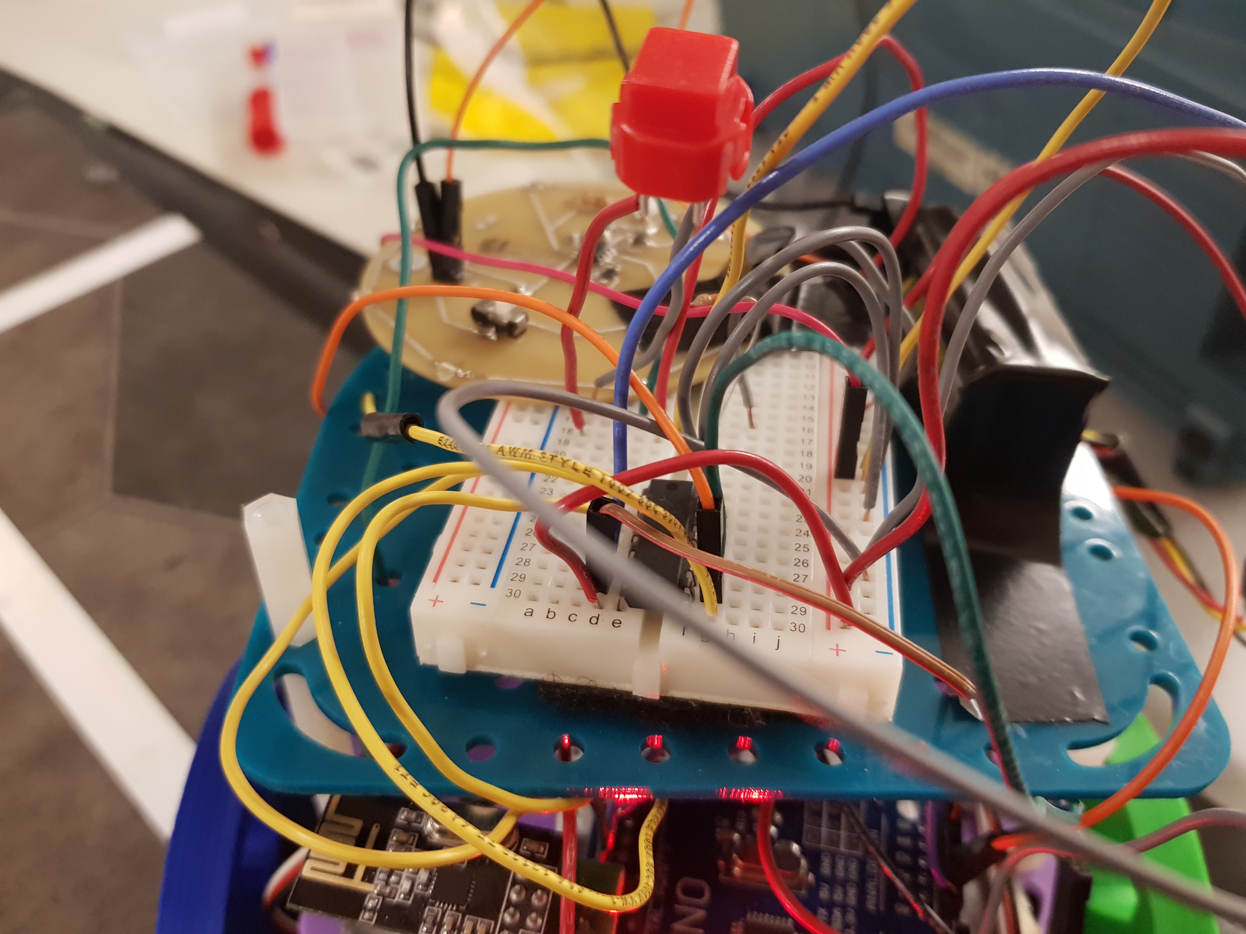
Layer Two
Layer two holds the Multiplexer (mux) and the push button. It also holds the IR hat. The mux provides extra places for analog inputs, and the push button provides a backup to the acoustic circuit, so just in case NVR doesn’t hear the 660Hz signal, we can directly tell him to begin his journey.
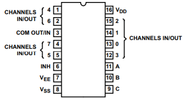
We added a mux in order to have more analog input pins, so NVR has more sensors to learn about the maze he is exploring. The mux allows us to add a third wall sensor and a third line sensor. The mux works by setting its select pins. Setting the individual select pins HIGH or LOW allow us to read the values of the sensors connected at each of its input pins. Each select pin (A,B,C) connects to a digit input (2,3 and 4), and the mux output (COM OUT/IN) connects to analog pin A2.
int readSensor (const byte which) {
  // select correct MUX channel
  digitalWrite (addressA, (which & 1) ? HIGH : LOW);  // low-order bit
  digitalWrite (addressB, (which & 2) ? HIGH : LOW);
  digitalWrite (addressC, (which & 4) ? HIGH : LOW);  // high-order bit
  // now read the sensor
  return analogRead (mux);
}
The pushbutton has two wires that connect to NVR. The the red wire connects to the 5V power. The grey wire connects to digital pin 7 on the arduino. That row on the breadboard also connects a 10KΩ Resistor to ground. As is, the pushbutton sends 0 to the arduino. However, when the button is pressed, the pushbutton sends 1 to the arduino. We have added this functionality to the detectAudio() function, as a second way to break out of the infinite while loop.
while(1){
   if (digitalRead(pushbutton) == HIGH){
      break;
   }
}
Software Unit Description
Turn
NVR keeps his sensors firmly on either side of the white line to follow it, thus, after writing to the servor motors it uses a small delay of 12 milliseconds combined with the while(analogRead(left_turn) < WHITE) to determine how long it should turn right, and while(analogRead(right_turn) < WHITE) to turn left.
Intersection Tracking
The line following is implemented using three line sensors. The line sensors continuously monitor their value and make correction while traveling in a straight line. Upon detecting white values on all three sensors, the robot will know that an intersection is found. Then it will make decisions about its traveling direction based on the maze information and the wall sensor information.
However, there are two possible cases which can result in a false positive: the robot believing an intersection exists where none those:
1) when the robot reads the same intersection several times due to the baud rate being far larger than the speed of the robot, resulting the main loop being repeated several times
2) when the robot is self-correcting (usually after turning), as it attempts to regain it’s proper position and sweeps it’s sensors from left to right all of the line sensors sometimes read white.
To this end, NVR has a system of three global flags that helps it seperate the false positive from the true positives.
interflag is instantiated as zero, and set to 1 when all three sensors read white; when all three sensors are not reading white, it is reset to 0. UpdateFlag represents whether or not that intersection has already been discovered, it begins as 1, and set to 0 after the first update completes, and is reset to 1 when all three sensors are no longer reading white. By making the condition for determining an intersection if (Interflag && UpdateFlag), NVR only updates the number of intersections the traversed the first time it senses it -- this resolves the first case discussed above. To resolve the second case NVR also has another flag, denoted errorflag. errorflag is instantiated as 0 and represents when the robot is in the process of self-correcting line following. In the line following function go_straight()there are three conditional statements that determine the robot’s behavior at any given moment: if (abs(error) <= ERROR_RANGE), else if (error > ERROR_RANGE), else if (error < -(ERROR_RANGE)). The first condition represents that the robot correctly positioned over the line with minimum error, the second when the robot is too right and the third when the robot is too left. If the robot is either too right or too left, it will begin self correcting. Thus, errorflag is set to 1 in these conditions, and reset to 0 in the first condition where error is minute. NVR is able to only detect true intersections through the condition if(interflag && updateFlag && ~errorflag).
Maze Traversal
As NVR travels through the maze, he has to make decisions. He uses walls to determine where he’s allowed to turn, but often has more than one possible direction to travel in. NVR uses a DFS algorithm to determine his next position. Given his unique and vibrant personality, you will probably not be surprised to hear that NVR see the world in a very unique way. Consider the unexplored terrain of the final competition: the only thing known is that the strange land is nine squares in length, nine squares in width, and surrounded on all the perimeter with walls. But what lies inside is a mystery, one which fills NVR with unfathomable depths of wanderlust. However, NVR is picky: he want to go everywhere: explore each and every node in this mysterious land, take note of every wall, but he does not like to waste time by going nodes he has already visited.
Each node has it’s own number. To determine the xy coordinates of the number simply use the following conversion: X = rem(#,9)-1; Y = floor(#/9) where the # represents the node number. Node 1 correlates to (0,0) Node 10 (0,1) and so on. To keep track of where he has gone, and where he wants to go, NVR has two 1x81 arrays of zeros (path and frontier), each of which has their own pointer (curpath and curfront). Path has a second pointer called lastBranch, a counter variable numTraversed that keeps track of how many nodes have been visited, and a global int newpos that describes the next position NVR will visit.
When a new location is traversed, the corresponding number to that location replaces the zero in path.
Example: 5 points have been traversed and no wall encountered, then path[81] = {1,10, 19, 28, 37, 0, 0...0}. and curpath = 4. curpath is the pointer to path (gives the indice that corresponds to the current position, curpos = path[curpath]. Frontier is also an array (this was to avoid adding the same value to the frontier multiple times, as stacks can not be searched) that keeps track of the points NVR wants to visit. curfront is the pointer to the frontier. In the above example (assuming that 2, 11, 20, 29, 38 do not contain any walls), the frontier = {2, 11, 20, 29, 38, 0, 0...0} and curfront = 4. lastBranch is a pointer to the indice in path that would led to the latest frontier point. numTraversed is the total number of new points traversed by the robot at any given moment (in the example it would be 5). This was done because dynamic memory allocation is difficult and computationally expensive in Arduino
The path begins with the indice 0 set to 1. This is because even though NVR did not technically see the node with his line followers, he is standing over it and feels that that is close enough. Really, NVR can be quite temperamental at times.
This is the main loop that determines NVR’s actions at any given moment:
if(path[curpath] == 1){
    updateFrontier();
  }
  go_straight();
  if(interflag && updateFlag && ~errorflag){
    updatePath();
    updateFrontier();
    decideNextDir();
    updateFlag = 0;
  }
NVR then updates frontier (the place he could have gone, and will go later) by checking for the presence of walls on the right and left and searches through the path and frontier array to ensure that the potential positions have not already been traversed. After ensuring that the left and/or right position was a new, viable option, it is added to the frontier. updateFrontier also included a call to updateFrontierWPath(), which checks if the point that was just traversed and added to path was also in the frontier. If it was it replaces it with 0, and shifter the frontier positions and pointer back to reflect the new frontier. If there is any new addition to the frontier, lastBranch is updated accordingly.
decideNextDir() decides the next direction of NVR. It takes the current position and checks the front, left and right wall sensors. If it is possible (if the position is not blocked by a wall and has not yet been traversed) then NVR continues to go straight -- dir does not change. If there is a front wall or the position ahead is blocked, then NVR checks if it possible to turn right (N=>E, E=>S, S=>W, W=>N). If right is a viable option, dir is updated accordingly and turn(right) is called. If it is not possible to turn right (if it location is already traversed or blocked by a wall, NVR checks if he can turn left. Likewise if left is viable option then dir is updated and turn(left) is called. If NVR can not turn left, the function moveDFS() is called. decideNextDir() also leads where NVR sends back messages to his friend the PC about the walls he has seen. moveDFS()compares NVR’s current position (curpos = path[curpath]) and the last position where he could have options to go somewhere new (indicated by the frontier): branch = path[lastBranch]. The new location NVR wishes to go to is denoted newfront = frontier[curfront]. To get to this new position NVR begins his arduous journey. First, he determine which of his neighboring four points would be the best option by eliminating the ones blocked with walls and choosing the oldest of the remaining (nextloc = findOldest(curpos)). Then the function getDirnMove(curpos, nextloc) is called, this function get’s the direction and turns the robot accordingly so that it faces nextloc while it is situated on curpos. For an example if the nextloc was 5 and curpos was 4 the robot would turn right and set dir to 3 (East). The robot then moves forward until reaching the next intersection (which is nextloc). The curpath pointer is updated accordingly. From that point, the robot traversed backward until it reaches the position described by branch. After reaching branch NVR turns one last time so that he faces the newfront (the latest position in the frontier) and resets the curpath position (curpath = numTraversed-1). Now, the next time the loop begins, NVR will be facing an viable position that is new and not blocked by any wall. Work Distribution
The Lab Report Work Distribution is as follows:
- Priya: Started the initial report draft
- Joyce, Nathalia, Vini: Added their contributions
- Nathalia: All Pictures and Videos
The website work distribution is as follows:
- Nathalia: Website Set Up and Maintenance